Airframe aerodynamics
The basic setup is in step 7 of the conversion. This page is the detail behind it.
Drag area
Drag Area is an equivalent flat-plate area. Basically, how big a flat plate would have to be to make the same drag.
- Front (Z) is usually 1–1.5 m² for light helicopters and 2–3.5 m² for medium ones.
- Side (X) and top (Y) can start at the model's side view and top view areas, then get tuned from there.
- The Mi-8's big side and top numbers were fitted to published stability data. Don't copy them.
Fuselage only, or fuselage and boom? Only split the drag between the two bodies if your data is split that way, or if you're estimating each part off the model. If your numbers are for the whole aircraft (a published total flat-plate area, or values fitted to whole-aircraft stability data), put it all on the fuselage and leave the boom's Drag Area at 0 0 0. Otherwise the boom gets counted twice. The Mi-8 does it this way, its fuselage carries the whole airframe and the boom is zero on purpose.
Side (X) and top (Y) Drag Area push on the aircraft with the square of the sideways or vertical airflow. You get the full force in a pure sideslip, in the hover downwash or coming straight down, and only a few percent at normal cruise attitudes. They don't make the fuselage lift.
Aero Half Extents is half the fuselage's width / height / length. If all three are set, that's the box RFM samples downwash over.
Directional Area Cap limits how big the effective area can get at big sideslip angles. 0 = no cap.
Measured shape (recommended)
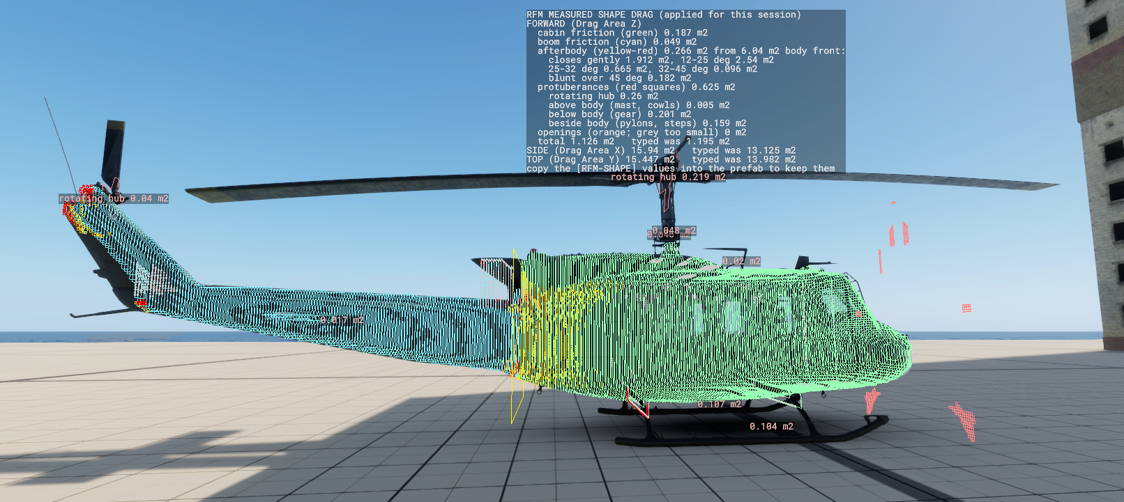
Instead of guessing numbers, RFM can work out the fuselage drag from the aircraft's actual shape. This is what I'd use if you don't have good data.
- On the Flight component, tick Measure Airframe Shape (80 Diagnostics) and spawn the aircraft. Two seconds after it spawns, it slices the aircraft front to back and traces rays through every slice from four sides. It only does this once, spread over a few tens of seconds. A yellow label counts down and shows progress, and the slice outlines show up in yellow as they're measured.
- Look over the aircraft:
- Green outlines (every 5 cm): the cabin as the airflow sees it. Open cabins count as inside the body.
- Cyan outlines: the tail boom.
- Yellow to red squares on the back of the body: rear surface where the airflow breaks away because it closes up too steeply (a blunt end, a steep upsweep). Yellow is partly separated, red is fully. Gentle tapers don't get marked. The panel lists the rear surface by angle.
- Orange dots: openings (doors off, open crew compartment), counted as cavity drag. Grey dots are holes too small to matter in flight (windows modelled as holes, gaps), so they aren't counted.
- Yellow frame: where the cabin meets the boom.
- Red squares in front of the nose: protuberances, so everything sticking out of the body (landing gear, hub and mast, aerials, wire cutters, fittings, tanks). Short parts count as bluff drag, and long parts like fuel tanks and pods count as streamlined. The panel splits them into above, below and beside the body. The rotor hub counts by the area its parts sweep while turning. Labels on the aircraft show the drag of the biggest bits. The fin, stabiliser, parked blades, mounted weapons and crew are left out since they have their own drag.
- A floating panel lists every part's drag, plus the forward, side and top totals next to what you typed in.
- The result gets applied right away, so you can go fly it. To keep it, copy the eleven
[RFM-SHAPE]values from the log into the fuselage Drag Body's Measured Shape fields (same names), save, and turn the switch back off before you release.
A few more things about it:
- With Shape Cabin Length M and Shape Cabin Section M2 set, the fuselage Drag Area gets replaced. Front (Z) uses the built-up value (skin friction with some allowance for rivets and joints, afterbody separation, protuberances, the rotating hub and openings), and side (X) and top (Y) use the measured outlines times a cross-flow drag coefficient. The startup log prints the breakdown.
- Doors, ramps and glass get measured the way they are when it runs (attached parts count), so open or close them before spawning to match what you want.
- It traces the detailed hit geometry that bullets use, which is close to the visible model. If a model doesn't have that, it measures the collision shapes instead and the log tells you. If a part looks wrong in the drawing, fix that number by hand in the Measured Shape fields.
- Stores, the fin and the stabiliser have their own drag, so they aren't part of this.
Fuselage moments
The bare fuselage's pitch, yaw and roll moments come from Body Pitch / Yaw / Roll Moment Coefficient (step 7 of the conversion). Two extra fields help when your data comes from a wind tunnel report:
| Field | What it does |
|---|---|
| Body Moment Reference Incidence Deg | The angle between the axis the moment data was measured against and your model's forward axis, positive when the data's axis points nose up of the model. Reports usually measure against the fuselage reference line, and a model's forward axis is rarely the same line. Without it, the data's zero ends up at the wrong attitude. The H-47 uses 4. |
| Body Yaw Moment Incidence Shaped | Scales the bare-fuselage yaw moment with the fuselage angle of attack, as sin(angle of attack + Body Yaw Moment Incidence Phase Deg). That's how NASA TN D-8159 fits the CH-47. Off, the yaw moment ignores angle of attack, which is what older prefabs do. |
| Body Yaw Moment Incidence Phase Deg | The phase for the shaping above. 20 for the CH-47, so the moment is about a third of its full value at level attitude, zero at 20° nose down, and stabilising past that. |
Leave all three alone unless your data actually works that way. A long fuselage like a Chinook's can yaw itself off at speed without the shaping, a short one usually doesn't care. [RFM-YAW] in the log (Debug Log on) shows the bare-body yaw moment and how much of it the shaping leaves.
Fin and stabiliser
- Set Area and Span.
- Leave Cl Alpha, Cl Max and Cd0 at their defaults unless you have data.
- Incidence Deg adds on top of the PointInfo angle, so don't set both to the same angle.
- The fin's normal defaults to sideways (+X) and the stabiliser's to up (+Y). The log tells you when RFM fills these in.
Extra surfaces (Flight, 13)
Add one RFM_SurfaceConfig for every extra wing, fin, endplate, rudder or canard.
- Place it with its own Point (category 02 Placement). With Surface Frame From Point Orientation on, the Point's rotation sets which way it faces too.
- Tick Vertical for fins, rudders and endplates.
- Set Area and Span, and a Name for the log (like
wing.left). - Control-linked incidence (category 03) adds degrees per unit of control. An elevator uses Incidence Per Long Deg, ailerons use Incidence Per Lat Deg with opposite signs left and right, and a rudder uses Incidence Per Yaw Deg. The Fin and Stabiliser slots have the same fields.
- Stub wings (Mi-24, AH-64): one horizontal surface per side at the wing's real incidence. Draw Airframe shows every surface so you can check them.
Surfaces can't be scheduled by airspeed yet (like the UH-60's stabilator).