Step-by-step conversion
Go through these in order and test after each group. Every step does one job, so when something breaks you know which step to go back to.
Step 1: Addon and inherited prefab
- Make your addon. Add RFM (GUID
6A4320961CBBA026) and whichever addon owns your aircraft model as dependencies. - Make a prefab in your addon that inherits from the working vanilla (or upstream mod) aircraft. Don't edit the upstream prefab itself.
- Keep the native vehicle body, collision, compartments, helicopter controller, engine actions, animation and replication. RFM's script patches spot the Flight component and reroute the controls and engine start on their own.
- RFM needs a vanilla-style helicopter underneath it. That means a
VehiclewithVehicleHelicopterSimulation, the helicopter controller and its engine actions. If the upstream mod flies with its own script, turn that script off first, or the two flight models will fight each other.
Step 2: Add the components
Put RFM_FlightComponent on the vehicle root (the entity with the rigid body). Add the others from the components table as you need them. Both templates have the full set (flight, network, visuals, damage bridge and control overlay). If you're doing a twin on wheels, the Mi-8 is the better one to copy from.
Step 3: Aircraft Setup switches
Set these on the Flight component. Most of them are already the default, but Read Input isn't.
| Field (category) | Set to | Why |
|---|---|---|
| Apply Forces (01) | on | RFM moves the aircraft |
| Suppress Stock Sim (01) | on | Turns off vanilla flight physics |
| Stop Stock Sim Engine (01) | on | Stops vanilla's engine from flying the aircraft |
| Disable Autohover (01) | on | |
| Lock Stock Controls (01) | on | |
| Read Input (08) | on | If it's off, the aircraft uses the fixed test controls |
| Analog Input (08) | on (default) | Reads joystick controls as axis positions. Keyboard, mouse and gamepad players fly through the flight assist (10D Flight Assist). |
| Use Vanilla Engine State (06) | on | Cockpit start and stop work like normal |
| Substeps, Performance Profile (01) | Small or light aircraft: 3 / 1 (UH-1). Big rotors or lots of blades: 2 / 2 (Mi-8). | Accuracy against cost, see Performance |
Leave everything in categories 82–86 Diagnostics off. Especially Hover Test, Force Only and Spawn Lift.
On the native NwkHeliMovementComponent, set Enabled to 0. RFM's network component takes over its job.
Step 4: Build the flight topology
On Flight Topology Config, create an RFM_FlightTopologyConfig. The quickest way is to open the closest template next to your prefab, rebuild the same structure in yours and change the numbers. Every field is covered in the Flight topology pages, starting at Power groups, engines and shafts. The minimum you need:
4a. One power group.
- Set Id to
drivetrain.main. - Inside it, create an
RFM_MultiEngineSystemConfig(System) with:- one Source per engine, each with an Engine Config (
RFM_PowerplantConfig) - one Output Branch per rotor shaft
- one Source per engine, each with an Engine Config (
- Set Governed Rotor RPM to the main rotor's 100 % RPM.
- Fill in each engine's Rated Power, Transmission Limit (both in watts) and Governed RPM. They start at 0, and the power group won't build until they're set.
- Leave Sources Running At Spawn off so the aircraft spawns cold.
4b. One rotor unit per rotor.
- Give each one its own Id (like
rotor.mainandrotor.tail). - Set a Role: 1 = lift, 2 = anti-torque.
- Fill in an RFM_RotorConfig with the blade data. New rotor configs start empty, and the rotor won't build until Blade Count, Radius, Chord, Nominal RPM, Spin Direction and the collective range are set. The log tells you what's missing. After that, set the hub type fields in group 03 (see the hub table).
- Place the hub with Hub Point or Hub Bone.
- Fill in the Power Group Id and Power Output Id that drive it.
4c. A control map per rotor. This tells each rotor which pilot controls move it. A main rotor usually doesn't need one (leaving it empty means collective to collective and cyclic to cyclic). A tail rotor needs yaw mapped into its collective. See Control maps.
4d. Wake links. On a main and tail aircraft, add one link from the main rotor to the tail rotor.
4e. Reference IDs.
- Reference Rotor Id: the main lift rotor.
- Anti Torque Rotor Id: the tail rotor.
- Reference Power Group Id: the power group.
If you leave these empty RFM picks sensible defaults, but I'd fill them in so it's obvious. They decide which rotor drives the visuals, damage and gauges.
Check: spawn it and read the [RFM-TOPOLOGY] lines. Each rotor's hub <x, y, z> has to match where the rotor actually is on your model.
Step 5: Mass, balance and fuel (category 02)
| Field | What to put in |
|---|---|
| Empty Mass | Empty weight in kg, not counting crew, fuel and removable weapons (those get added separately). It's required, the flight model won't start at 0. |
| Empty Mass Point | PointInfo at the empty aircraft's centre of gravity (CG). If you leave it unset, RFM tries the Mass Centre Bone (empty by default), then falls back to the model's native centre of mass. |
| Empty Inertia | Rotational inertia about pitch / yaw / roll (X / Y / Z), kg·m². All three have to be above 0 or the native body inertia gets kept. The worksheet shows how to estimate it. |
| Override Inertia | On for a new aircraft, so your researched inertia actually gets used (Mi-8). The Huey keeps it off because its native inertia was already right. |
| Override Mass | On |
| Fuel Capacity | Usable fuel in kg. 0 or less turns RFM fuel off. |
| Fuel Point | PointInfo at the middle of the fuel tank |
| Fuel Fraction | Fuel at spawn, 0–1. Ignored while the vanilla fuel bridge is on. |
| Use Vanilla Fuel | On by default. The vehicle's stock fuel tanks become RFM's fuel, so Zeus fuel %, refuelling, jerry cans, leaking tanks and the cockpit fuel gauge all work off the same fuel RFM burns. Fuel Capacity maps to the stock tanks' total (50 % in Zeus is 50 % of Fuel Capacity). Does nothing on a vehicle without stock fuel tanks. Tanks fitted after spawn (extended-range tanks, fuel system mods) are picked up within about 5 s, and Fuel Capacity grows with them at the same kg per litre. |
| Burn From Current Tank | Off by default. When it's on, RFM burns from the tank the stock engines would draw from (the fuel consumption component's current tank) before touching the others. Turn it on if you're using a fuel system mod that picks the feed tank, like AHC Fuel Systems (tank valves, aux and external tanks). |
| Use Vanilla Fuel Consumption Scale | Off by default. When it's on, RFM's burn gets multiplied by the server's vehicle fuel consumption scale (8 in vanilla by default). Off is real-world burn. |
| Live Occupant Mass, Live Cargo Inventory Mass, Live Supply Mass | On, to weigh the actual crew, inventory and supplies |
The native Arma body's centre of mass can't move after spawn, so RFM tracks the real loaded CG itself and applies its forces around that. When you're checking balance, go by RFM's CG readout and not the Workbench COM gizmo.
Step 6: Ground contact (categories 15–18)
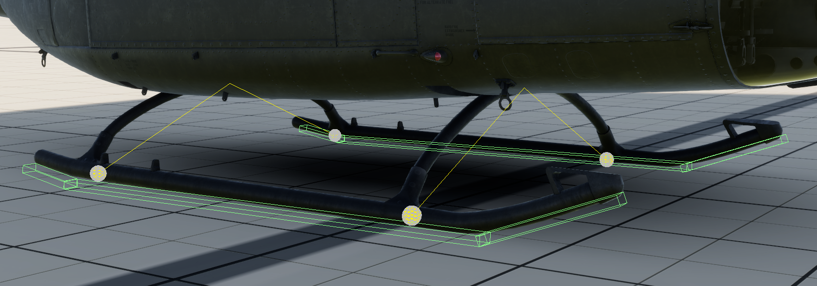
Pick a Ground Gear Mode: 0 = skids, 1 = wheels, 2 = none.
Skids (UH-1). There are two separate things to set up:
- Custom Skid Supports are the structural struts (the cross tubes). Each one has a Body Attach point (where it meets the fuselage), a Skid Attach point (where it meets the skid), a spring rate, a damper and travel. Tick Mirror Across Centerline and you only have to do one side.
- Custom Skid Contact Areas are the runner shapes that touch the ground: centre point, length, width, height, pitch and yaw. The Huey uses a main runner plus the turned-up lips at the front and back.
Wheels (Mi-8). Same idea, two separate lists:
- Wheel Struts are the oleos. Body Attach and Axle Center together set which way the strut compresses, then there's preload, spring, travel and steering.
- Wheel Tires are the wheels themselves: which strut they're on (Strut Index), Wheel Center, radius, tire stiffness, friction and brakes. Two tires can share a strut for twin wheels.
Wheel brakes use the vanilla wheel/parking brake key (Space by default).
Then go to the native VehicleHelicopterSimulation → LandingGear and set every wheel or skid SpringRate, CompressionDamper and RelaxationDamper to 0 (both templates do this). RFM handles the suspension now, the native gear is only kept for animation.
Check: spawn it cold and wait 10 seconds. It should settle and sit still. No creeping, bouncing or sinking.
Step 7: Airframe aerodynamics (category 13)
The fuselage and tail make drag, weathervane the nose into the wind and hold the pitch attitude in forward flight.
| Field | What to put in |
|---|---|
| Fuselage Config + Fuselage Point | A drag body at the cabin's aerodynamic centre. Drag Area X / Y / Z = side / top / front equivalent flat-plate area in m². |
| Tail Boom Config + Tail Boom Point | Optional second drag body for a long tail boom. Leave its Drag Area at 0 if your fuselage numbers already cover the whole aircraft (see Airframe aerodynamics). |
| Fin Config + Fin Point | Vertical fin: Area, Span |
| Stabiliser Config + Stabiliser Point | Horizontal stabiliser. Rotate the PointInfo to its real installed angle (the Mi-8 uses −6°). |
| Extra Surfaces | Anything else that makes lift: stub wings (Mi-24, AH-64), a second fin or endplates, rudders, canards. Each gets its own Point, Area, Span and optional control-linked incidence. See Airframe aerodynamics. |
| Reference Airframe Fallback | Off. When it's on, anything you didn't set gets filled with built-in Huey data. Only the Huey uses it. |
| Body Pitch / Yaw / Roll Moment Coefficient | 0 (default) unless you have data. The Huey's 13.95 comes from NASA measurements of that airframe. |
| Disable Elevator Link | On. The linked elevator schedule is Huey only. |
A part that isn't set or has zero area just does nothing, so that's a safe place to start. Details and estimates are in Airframe aerodynamics.
Step 8: Remove leftover vanilla physics
NwkHeliMovementComponent→ Enabled 0 (step 3).- Native landing gear springs → 0 (step 6).
- On
VehicleHelicopterSimulation → Simulation → Hull, set FrictionForceX/Y/Z to 0 (the Huey does this). - If the aircraft still has forces you didn't put there (like a pull to one side with Apply Forces off, or weird damping), zero the native helicopter sim's stabilisation, friction and bank-turn force amounts, and its native rotor force, torque and cyclic authority. Keep the controller, pivots, animation and signals.
- Leave Damping Cancel and Coulomb Cancel (category 01) at 0. Only touch them after you've measured a leftover spin-down loss on your aircraft.
Step 9: Presentation
Add RFM_VisualsComponent and turn Flight Publish Signals (category 19) off. Wheel strut and wheel spin animation keep working either way. Visuals can turn the rotors two ways:
- Rotor Visuals entries (Mi-8): add one Extra Rotor Visuals entry per rotor,
rotor.mainandrotor.tailincluded, each with the Child Bone its model uses (Mi-8:v_rotorandv_tail_rotor). Leave Drive Spin and Drive Mast Tilt off. Keep writingMainRotorRPMandTailRotorRPMso the graph still does blade coning, blur and gauges, but set theMainRotorAngleandTailRotorAnglerows to Scale 0.- Why Scale 0 on the angle rows? A lot of vanilla graphs fake the spin at speed using a timer and the rotor RPM, and it strobes. The rotor looks like it slows down and then runs backwards near full RPM. Scale 0 stops the graph adding its own spin.
- Turn Lean With Disc on for the main rotor entry so the drawn rotor leans with the simulated disc.
- Drive Spin (UH-1): Visuals moves the main and tail rotor children itself and can lean the mast with the disc (Drive Mast Tilt).
Either way, take the cyclic tilt out of your rotor's animation graph. Vanilla graphs tilt the blades for cyclic using bones inside the rotor model (v_cyclic, v_cyclic_bend and a "Cyclic blur" node). Once RFM is turning the whole rotor model, that tilt turns with it and the blades rise and fall once per revolution at a fixed spot, which looks wrong. Make a copy of the graph (.agr and .agf) in your addon, set those nodes' Expression to 0 in the rotor sheet, and point your prefab's VehicleAnimation AnimGraph at the copy. RFM's disc lean replaces the tilt, and it shows the real simulated tilt instead of just stick position.
Both ways turn the model at the exact simulated blade angle, so the rotor you see matches the real one at any speed.
Visuals also handles gauges, sound loops and camera vibration. See Visuals, sound, gauges and displays.
Step 10: Damage (optional)
Add RFM_ComponentDamageBridgeComponent and type your model's native hit zone names into its Zone fields: engine, gearbox, two tail drive shafts, main rotor, main rotor shaft and tail rotor. The log lists every hit zone on the aircraft ([RFM-DAMAGE] hit zones on this aircraft:), so just copy the names from there. If a zone can't be found it's treated as undamaged and you'll get a warning naming it. Twins and anything else with more than one engine use Engine Zones instead of the single engine field. See Damage, engine switches and rotor brake.
Flight helpers (Flight, 10C Flight Helpers): players turn the pedal helper on in the RFM settings tab, and these fields tune it per aircraft (Response and Authority). All the helper does is put in anti-torque pedal. It moves the pedal until the tail rotor's yaw moment cancels the main rotor's torque. It doesn't hold heading or coordinate turns. Raise Response if it lags behind collective changes, lower it if the pedal hunts back and forth. Player-side options (control device, key speeds, curves, HUD, units, camera shake) are in the game's settings menu under RFM, not on the prefab.
Rotor strikes (Flight, 20 Rotor Strikes) are on by default and don't need any setup, every topology rotor gets checked. When a rotor's blades hit terrain, something solid or water, it loses speed on every blade pass and the hub gets pushed, so a strike on one side throws the aircraft over. Strength sets how violent it is (lower is more forgiving), Water Hardness sets water against a solid obstacle, and loose objects lighter than Min Object Mass are left to vanilla collision. Vanilla rotor damage still applies on top.
Step 11: Weapons (armed variants only)
Add RFM_StoresMassComponent with one station per weapon position. See Weapons and stores.
Step 12: Multiplayer
Add RFM_NetworkReplicationComponent with its default settings, and make sure NwkHeliMovementComponent is turned off in every child prefab. See Multiplayer.
Step 13: Fly
Work through the first-flight test card.