Reading the log and debug drawing
When an aircraft spawns, RFM prints a readback of what it built. Check these lines before you fly:
| Line starts with | What it tells you | What you want to see |
|---|---|---|
[RFM-TOPOLOGY] generic topology path ACTIVE |
The topology loaded | It's there, with no ERROR lines near it |
[RFM-TOPOLOGY] resolved \| rotors 2 \| powerGroups 1 \| wakeLinks 1 |
How many of each thing got built | The numbers match what you set up |
[RFM-TOPOLOGY] power 'drivetrain.main' \| sources 2 \| outputs 2 |
Each power group | The right number of engines and shafts |
[RFM-TOPOLOGY] rotor 'rotor.tail' \| role 2 \| drive drivetrain.main/shaft.tail \| hub <…> |
Each rotor, its shaft and where its hub ended up | The hub is where the rotor actually is on your model |
[RFM] reference power system \| sources … \| driven inertia … \| outputs … |
The drivetrain as it was actually built | The inertias make sense (see Power groups, engines and shafts) |
[RFM-SETUP] … PointInfo \| local metres … |
Every PointInfo it found | The positions look right |
[RFM-DAMAGE] bridge \| ready… |
Whether damage hooked up | ready true if you're using damage |
[RFM-AIRFRAME-AUTHORING] … |
Default names or directions RFM filled in for your fuselage, fin and stabiliser | Just info |
[RFM-LINT] WARNING … |
The authoring check. It catches common setup mistakes like mismatched RPMs, missing inertia or lag damper, leftover template values and missing points | Ideally [RFM-LINT] authoring check \| 0 warning(s). Each warning tells you what to change. |
[RFM-TOPOLOGY] ERROR rotor '…' is missing: …, [RFM-SETUP] ERROR Empty Mass is 0 |
You haven't filled in some required data yet. New configs start empty on purpose, so nothing quietly borrows another aircraft's numbers. | Fill in the fields it names |
For live numbers while you fly, turn on Debug Log (m_bDebugLog, category 82). It prints flight state, engine, ground and per-rotor lines every Debug Log Interval seconds. If the log fills up too fast, bump the interval up (say from 2 to 4 s). That only changes how often it prints, the physics stay the same.
Turn it back off before you release. It's noisy.
Dump Bones (82) logs every bone in the model once at spawn, with its position and axes. It reaches child entities too, like a separate rotor model, as [RFM-CHILD-BONES] lines. Workbench doesn't show you bone positions, so this is how you get them.
Seeing what RFM sees: debug drawing
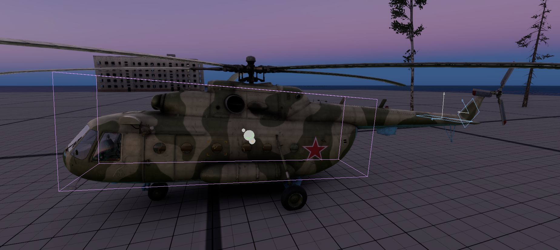
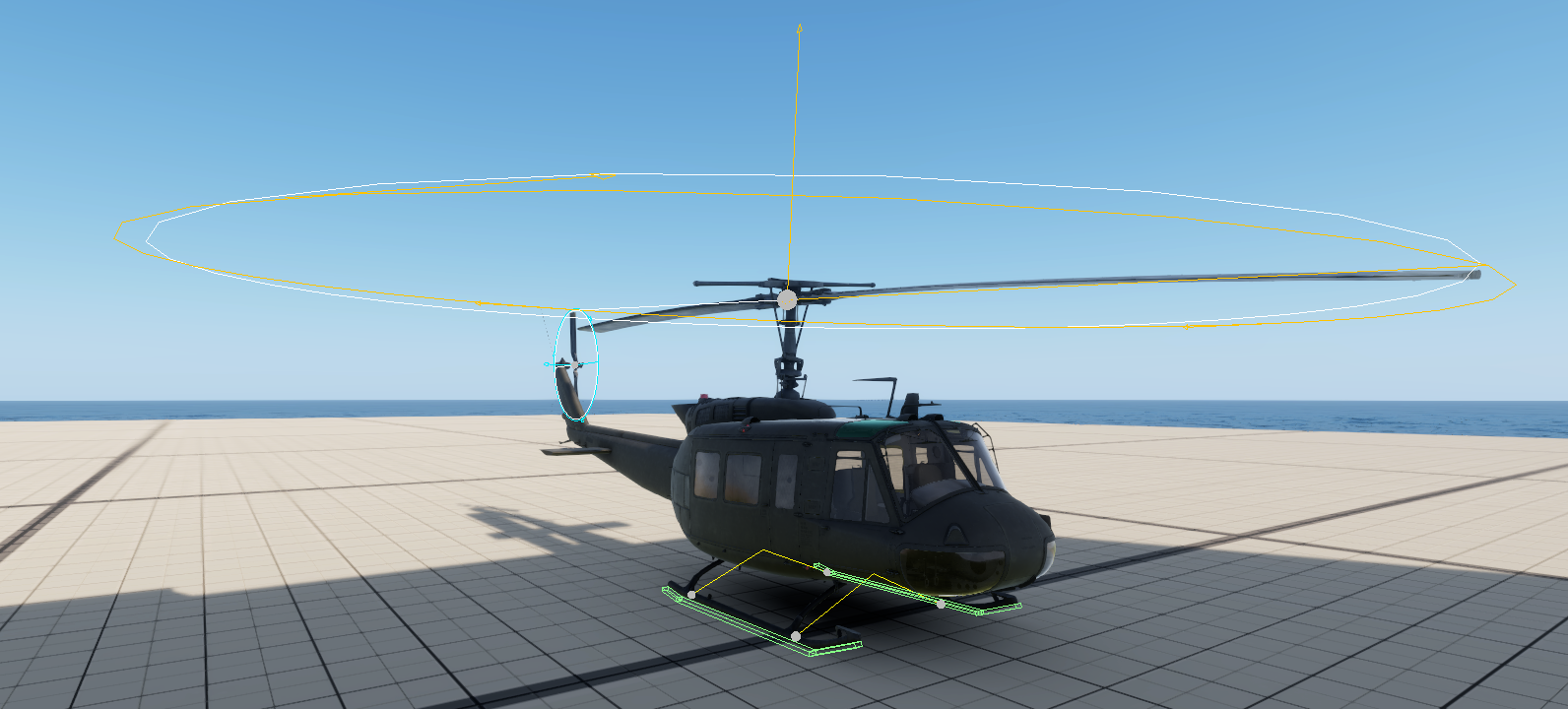
The log gives you numbers. Debug drawing actually shows you, right on the model, where RFM thinks every part is and which way it's pointing. Honestly this is the fastest way to catch a misplaced point. Turn these on in the Flight component under 81 Diagnostics - Draw and hit play. None of them change the physics.
| Switch | What gets drawn | What to check |
|---|---|---|
| Draw Rotors | For every rotor: • a circle at full radius in the shaft plane • a sphere at the hub • an arrow along the thrust direction • the blades where the sim has them (blade 1 is white) • three arrows on the rim showing which way the blades travel • a thin white ring for the tip-path plane (the disc as it's tilted by flapping) Orange is the main (reference) rotor, cyan is the anti-torque rotor, magenta is anything else. |
The disc sits on the model's rotor, it's the right size, and it leans with the mast. The tail rotor's thrust arrow points the way the tail needs pushing (Shaft direction and spin: getting anti-torque right). The rim arrows match the real rotation. |
| Draw Ground | Skids: the supports from body to skid (yellow) and the contact areas as green boxes. Wheels: the struts at their live compression (yellow) and the tires as circles, green when they're touching the ground and grey in the air. | The runners line up with the model's skids. The tires line up with the model's wheels, they're the right size, and they all go green when parked. |
| Draw Airframe | Drag bodies as purple boxes (the volume RFM samples downwash over), and the fin and stabiliser as blue rectangles (span × chord). Each surface also gets a white arrow for its normal and a blue arrow pointing along the chord to the leading edge. | The fin stands upright on the tail, the stabiliser lies flat at its real angle, and neither one is buried in the fuselage. Incidence Deg gets added on top in the solver, so you won't see it drawn. |
| Draw Mass | Spheres: green is the loaded CG, yellow is the native physics centre of mass, white is the empty airframe centroid, orange is the fuel centroid | The green CG sits close under the main rotor hub, and it moves when you add fuel, crew or cargo. |
| Draw Blade Motion | Articulated rotors only. Each blade as the sim has it: hub, flap hinge, lag hinge, tip. Flap and lag are multiplied by Blade Motion Draw Scale (3 by default) so small motions show. Green is normal, yellow means the blade is on or near a stop or moving fast, red means a runaway. The grey line is the same blade with no flap or lag, and the bigger tip ball is blade 1. | All blades cone up together and trace a smooth tilted circle. One blade sitting higher than the others, or a blade going yellow or red, is worth a look in the Blade Motion Diagnostic log. |
| Draw Through Geometry | On (the default) draws everything on top of the model so you can see inside the fuselage | Turn it off to hide shapes behind geometry |
The first frame with drawing on prints a one-line colour legend ([RFM-DRAW]) to the log.
For the numbers behind it, tick Blade Motion Diagnostic (82). Every Debug Log Interval (half a second at least, and it works with Debug Log off) it prints an [RFM-BLADE] line per rotor: each blade's lowest and highest flap and lag, its fastest hinge rate, its mean flap, the stop hits and the rotor thrust range. The same numbers show on a panel in the pilot seat. If a blade's flap or lag rate goes past Blade Runaway Rate it prints a RUNAWAY line straight away with everything that blade was doing.
Under it comes an [RFM-BLADE-STN] line for the blade stations, root to tip: the angle of attack range at each one, how often it was stalled (split into positive and negative angle), how often the air came from behind, and the swirl speed there next to the blade's own speed. With Draw Blade Motion on, a stalled station shows as a red ball on the blade and a reverse-flow station as a blue one. A hovering rotor should show no red at all.
On aircraft with more than one rotor, the [RFM-FLARE] line adds up the pitching moment from every rotor and then lists each one (per rotor noseDownNm rotor.fwd … rotor.aft …). A tandem pitches on the difference between its rotors, so that split is what you want when it pitches up or down on you.
The [RFM-YAW] line follows the force balance. It shows the fuselage angle of attack and sideslip, how much of the bare-body yaw moment is left after the angle-of-attack shaping, and the yawing moments about the CG: bare body, whole airframe, everything else (rotors, ground) and the total, all positive nose right. With Draw Airframe on you get the same thing 3 m above the CG. The grey line is where the nose points and the white arrow is where the aircraft is going through the air, so the gap between them is the sideslip. The orange arrows are the bare-body moment and the cyan ones the total, drawn at the nose and the tail at 1 m per 20 kNm. The nose arrow points the way the nose is being pushed.
The [RFM-ROTOR-LOADS] line (blade motion diagnostic on) takes every rotor aero pass in the window at the azimuth it was worked out at. The hub thrust and torque, the loads the hub actually passes to the airframe, are split into the average, the ripple a rotor of N blades passes on (N and 2N per turn, so 3P and 6P on a three-bladed rotor) and a non-periodic rms with its share of the average. Each blade is one blade's own load against where it is on the disc, split into the average and 1P to 4P, with where it is highest and lowest (0° = blade pointing aft, 90° = advancing side, 180° = forward, 270° = retreating side). On an articulated hub the blade spends most of its 2P-and-up airload flapping itself, so the hub ripple is a fraction of what the blade line shows. That is what a real hinge does. A healthy rotor's hub load is mostly average, with a modest N-per-rev ripple and little non-periodic load. Each [RFM-ROTOR] line ends with that pass's hinge relief: the newtons along the shaft and the newton-metres of torque that went into moving the blades instead of reaching the airframe. The line also gives the downwash other rotors put through this hub, which is how much of the front rotor's wake the rear one is flying in. With Draw Blade Motion on, a ring round each hub shows the blade load against the blade's azimuth, scaled to the whole rotor: the grey circle is the average and the ring bulges out where the blades carry more. The ring is green, yellow or red when the total's non-periodic part is under 10 %, under 30 % or over 30 % of the average.